
On Track With Lorac
|
What was Lorac and how did it work? |
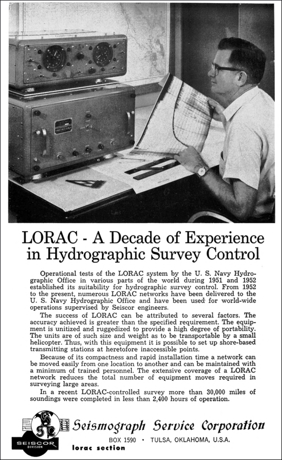
 Rendered obsolete by the now ubiquitous GPS, the Lorac radio navigation system became defunct and virtually forgotten. Very little information is available on the web about it and how it worked. A search will reveal a coast guard officer's masters thesis and a couple to oil survey field reports. Looking a bit deeper, some scholarly papers and a technical manual have surfaced that can help us understand how Lorac worked. And it worked pretty well. Lorac, meaning "long range accuracy", was a product of the Seismograph Service Corporation of Tulsa, Oklahoma, which owned the patents. Equipment was built by a subsidiary called Seiscor for both civil and military markets. They also supplied technical support in the field. |
 |
|
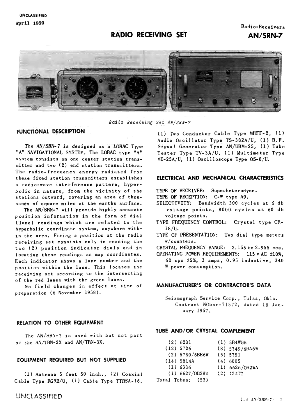
Originally intended for oil exploration surveys, semi-permanent Lorac transmitter chains covered the US gulf coast from Texas to the Florida panhandle during the late 1950s to 1960s. The US Navy was a big user of Lorac for inshore and coastal surveys as well as in sea searches to locate lost ships and aircraft. Ruggedized field deployable tactical transmitters and receivers were used by regular navy survey ships of that time. A photo of AN/SRN-7, the navy's Lorac receiver, is below. |
 AN/SRN-7 US Navy Lorac receiving equipment. From left: antenna coupler, indicator and receiver. |
|
While testing the newly installed SASS sonar, USNS Michelson used the Bahamas Lorac chain for several months during 1964. There were two sets of receiving equipment installed in the Survey Control Center. A field engineer from Seiscor came along for tech support. Position fixes were obtained from visual readings of the receiver phasemeters entered manually into the ship's Bendix G-15 general purpose computer. |
 Lorac
transmitters operated in the 1.7 to 2.5 mhz
medium
wave spectrum, then also the
home of Loran A and the 160 meter amateur (ham) radio band. This
is just above AM standard broadcast. Like Loran C, Decca, Omega
and some other radio navaids, Lorac was a "hyperbolic" phase
comparison system. Lorac
transmitters operated in the 1.7 to 2.5 mhz
medium
wave spectrum, then also the
home of Loran A and the 160 meter amateur (ham) radio band. This
is just above AM standard broadcast. Like Loran C, Decca, Omega
and some other radio navaids, Lorac was a "hyperbolic" phase
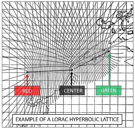
comparison system. The useful range of a Lorac system was a bit over 100 miles in the daytime, but perhaps half that at night due to skywave interference. Accuracy was said to be within 2 1/2 feet at best. There appears to have been two slightly different flavors of Lorac; the drawing below describes the variety used in the Bahamas in 1964. This was called Lorac B. |
 |
|
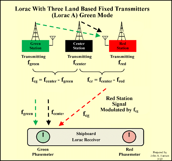
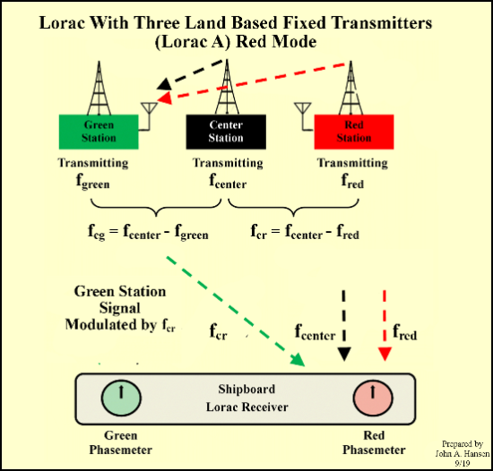
Three land based stations transmitting unmodulated continuous wave signals were called green, red and center. For example frequencies of the green and red stations might differ from that of the center station by 600hz and 240hz respectively. These three signals were received at the reference station and the difference signals (audible tones of 600hz and 240hz) detected. Amplitude (AM) modulated by the two tones, the reference station transmitted on a frequency unrelated to the other three but in the same band. Green and red stations did not need to be phase locked to the center station as minor variations would be reflected in the reference station's two modulating tones as well. Aboard ship, the Lorac receiver measured the difference in phase between the green/center 600hz difference (beat frequency) and the 600hz modulation on the reference station's signal. Similarly, the red/center 240hz beat frequency was compared with the reference station's 240hz modulation. Phase meters indicated the green and red phase differences. Mechanical counters kept track of the lane counts, a lane being about 80 meters wide along the baselines between station pairs. Width of Lorac lanes diverge from the green/center and red/center baselines since points of equal phase describe hyperbolas. Thus, Lorac was potentially very accurate as the smallest movement of the mobile (shipboard) receiver meant a large phase difference. Being that no means of lane identification was provided, Lorac receivers had to be calibrated at a known geographic position at the beginning of a survey. Another version of Lorac did without a reference station. The green and red stations alternately transmitted reference information in a time shared mode. Instead of radiating a single frequency, the center station switched between two different ones at about 10 times per second. Both center station frequencies differed from the green and red frequencies by audio tones, just as in the above diagram. This switched green/red mode was called Lorac A. |
 |
 |
|
Both the green and red stations were furnished with Lorac receivers. Green received the center and red signals and used the audio tone difference (beat) frequency to modulate its transmission during the "green mode". Similarly, in the "red mode" the red station modulated its signal using the center/green beat frequency. Another diagram of how the switched mode Lorac A worked can be found here. As well as being more economical, Lorac A switched mode was probably used to allow a greater choice of operating frequencies in the narrow band available. It also may have prevented interference from the adjacent Loran A chains which operated in the same frequency band. All of this was a bit more complex, but very clever, very accurate and worked essentially the same as the four station Lorac B.  Until
GPS came along Lorac was probably the most accurate radio navaid
for survey control. While it lacked the range of Decca and Loran
C it was widely used by the US Navy as well as by the oil
industry. Until
GPS came along Lorac was probably the most accurate radio navaid
for survey control. While it lacked the range of Decca and Loran
C it was widely used by the US Navy as well as by the oil
industry.An excellent system description of Lorac can be found in Review of Marine Navigation Systems and Techniques, archived on the web. This is dated 1965, a Department of the Navy, Bureau of Ships publication. Here is a link to the chapter on the Lorac radio navigator. The International Hydrographic Review, the journal of the IHO (Monaco), has published several articles about Lorac. The basics of Lorac A, the original version of Lorac, can be found in Hyperbolic Positioning Systems for Hydrographic Surveys, published in 1953. From 1966, Calibration of Lorac covers the more accurate Lorac B system (four station Lorac). This article also describes a then new lane identification feature. |
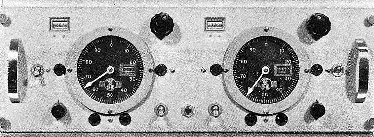
A commercial version lorac
indicator unit c. 1955.
The circular dials are
phasemeters.
Mechanical counters kept track of the lane count. |
|
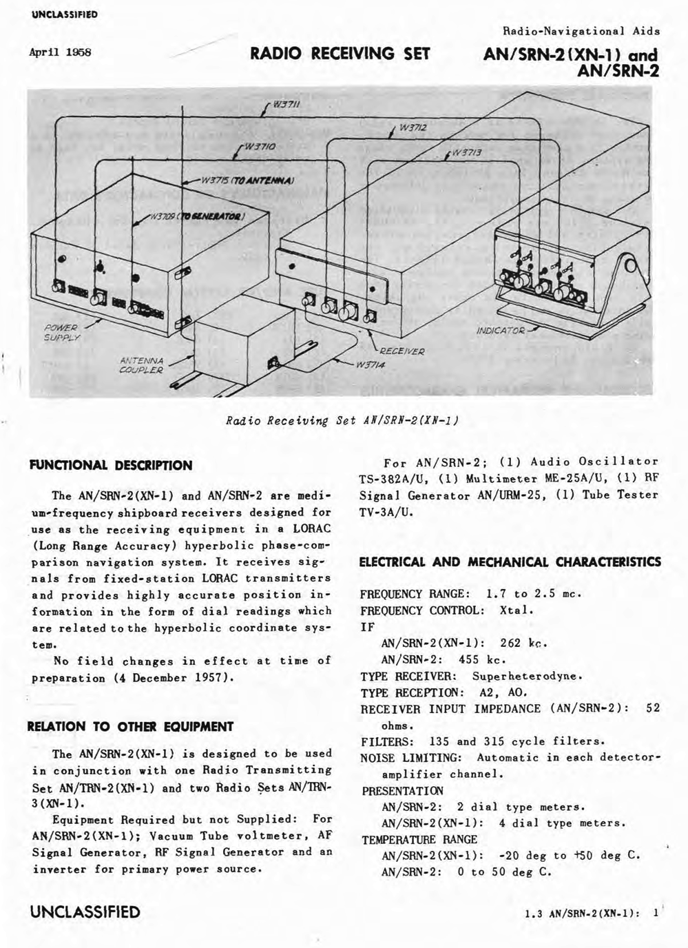
Militarized transmitters and receivers were furnished for use by the Navy. Below are technical details of two military grade Lorac receivers built by Seiscor. In addition to the receiver unit and antenna coupler a position indicator furnished time/phase difference readings on two dials. Mechanical counters kept track of lane count. Lorac types A and B did not have lane identification. |
 |
 |