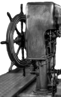
 The helmsman in the pilot house steered with a telemotor, a hydraulic device that controlled the ship's rudder
position. A mechanical gear arrangement converted the port or starboard
rotational movement of the ship's wheel to a piston in a hydraulic
cylinder. The helmsman in the pilot house steered with a telemotor, a hydraulic device that controlled the ship's rudder
position. A mechanical gear arrangement converted the port or starboard
rotational movement of the ship's wheel to a piston in a hydraulic
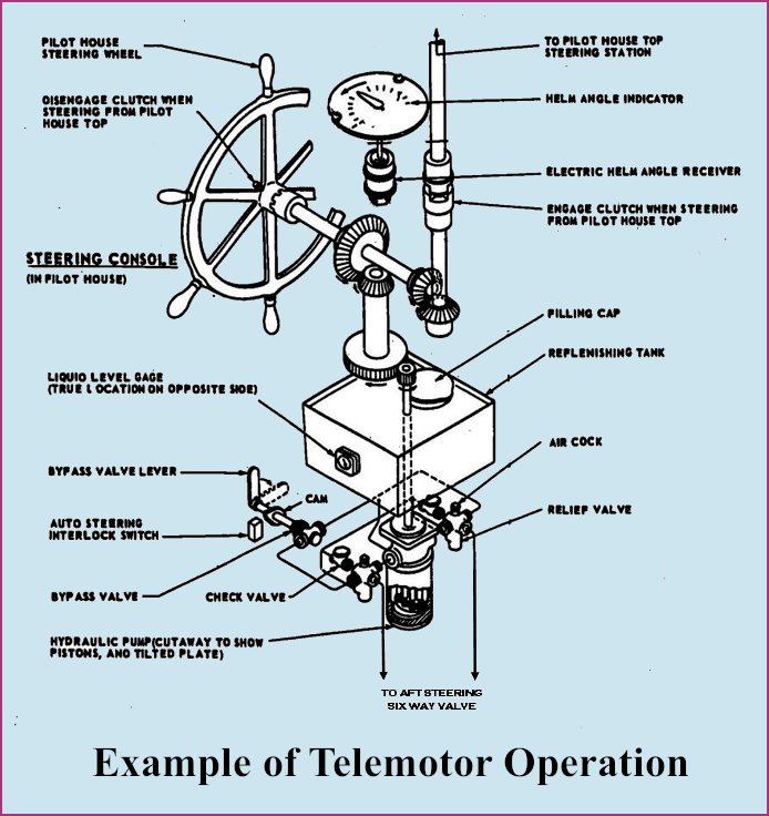
cylinder. Many, if not all, of these telemotors were built by a company in Beacon, New York that prior to WWII had made commercial baking machinery. According to the Dutchess Tool Company both the earlier Liberty Ships as well as Victories were fitted with their steering apparatus. Some Victory Ships had an additional steering position located just above the pilot house. A copper or brass pipe containing hydraulic tubing extended directly upwards from the telemotor through the overhead to the helm on the flying bridge. |
 |
| The diagram below gives a general idea of how a telemoter was constructed. Some were built with two hydrauluc cylinders, others had just one. |
 |
|
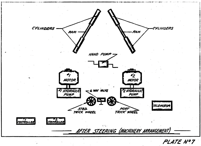
Hydraulic tubes extended back from
the telemotor helm on the bridge to the aft steering room, where the
helmsman's port or starboard movement of the wheel operated something
called a six way
valve. This device
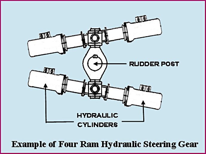
controlled the amount of hydraulic pressure applied to the cylinders at
either end of two large rams. Both rams were tied to the ship's rudder shaft. Two electrically driven pumps supplied the necessary pressure. Provision was made for emergency steering aft near the stern. While the pilot house telemotors were the same on Liberty and Victory ships the actual steering machinery differed. Steam power was used run the hydraulic pumps on Liberty ships. |

|
 |
 . .
|
|
Plates 7 and 32 above were taken from a set of drawings made in 1964 of the mechanical systems aboard technical research ship USS Liberty, a modified Victory VC2-S-AP3 hull, originally built as SS Simmons Victory in 1945. |