
Victory Ship Electrical System
| As Built in 1944-45: Direct Current |
|
The VC2-S-AP2 and VC2-S-AP3 Victory Ships were originally built
with all DC (Direct Current) power. DC was in common use at the
time aboard ships and in parts of some American cities, especially in
iudustrial areas. It is still widely used to power trains and subway
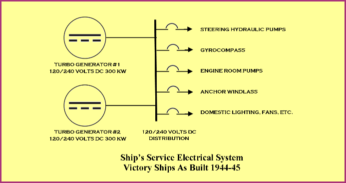
systems. Everything aboard the Victory Ships ran on DC, from the anchor windlass, to the pumps in the engine room and even the electric mixer in the galley. Direct current enables speed variation and high starting torque in electric motors. |
| Victories were built with a pair of steam powered turbo generators delivering 120 and 240 volt DC. They were rated at 300 kw (Kilowatts) each. Connected to a distribution board in the engine room, the generators' output was sent throughout the ship for domestic lighting as well as powering machinery. Steam at 450 psi (pounds per square inch) drove the generators' turbines. |
 |
|
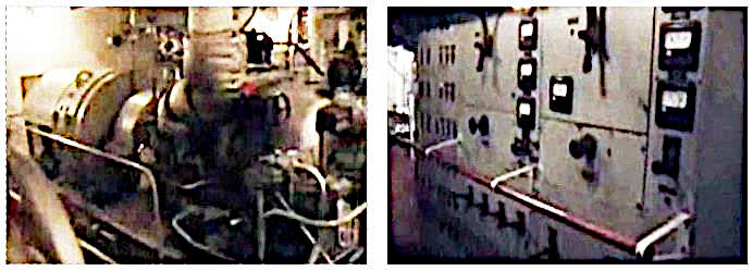
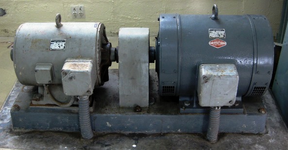
A turbo generator set in the left hand photo.The DC
generator is at left and steam turbine to the right. A DC
distribution board is in the right hand photo.
|
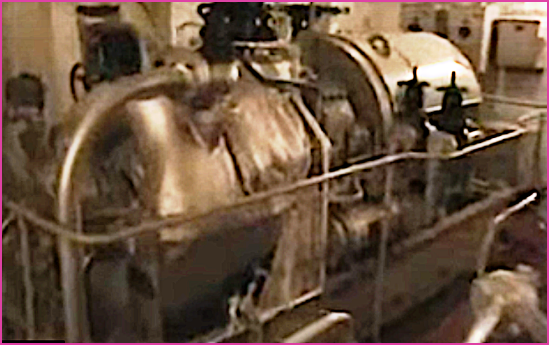  |
| More views of the turbo generator sets. The cylindrical device at the end of the turbine's shaft is part of the bearing lubrication system. Lube oil was pumped throughout the engine room to the bearings on rotating machinery. |
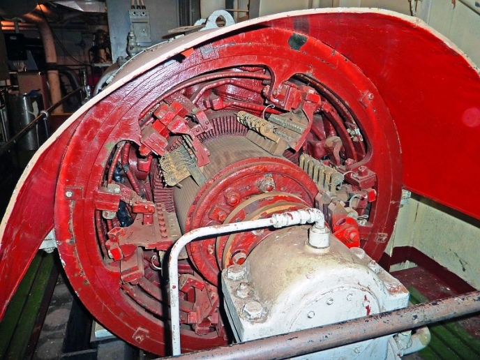 |
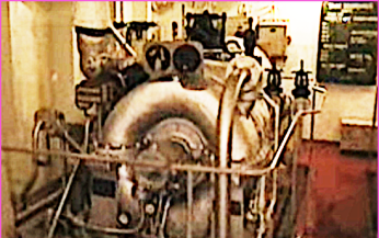
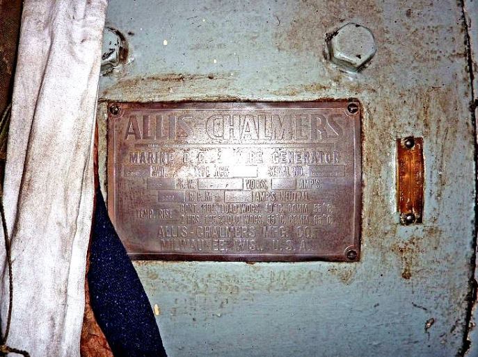
| One of the DC generators aboard museum ship SS Red Oak Victrory. The nameplate reads "Allis Chalmers, 300 kw, 1250 amps at 240 volts DC". At right the six sets of multple commutator brushes are needed to carry the high current. The bearing lubrication is painted white. Photos by Phil Brooks. |
 Some
electrical gear aboard the Victory Ships required power other than 120
or 240 volt DC. One of these was the Sperry Mark 14 gyrocompass, first
installed aboard ships in 1944. A motor-generator set (MG) driven by 120
volts DC delivered 50 volt three phase AC at 210 hertz to the
gyrocompass. Some
electrical gear aboard the Victory Ships required power other than 120
or 240 volt DC. One of these was the Sperry Mark 14 gyrocompass, first
installed aboard ships in 1944. A motor-generator set (MG) driven by 120
volts DC delivered 50 volt three phase AC at 210 hertz to the
gyrocompass. A photo of the Mark 14 and the associated MG set aboard SS American Victory is at the right. A Mark 14 technical manual can be found online here. |
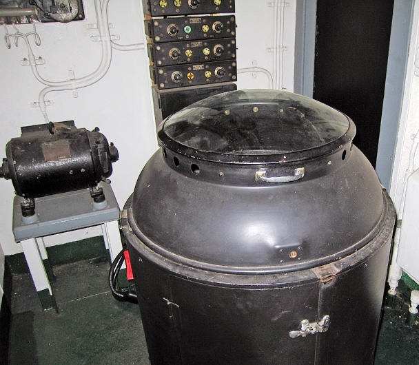
| Emergency generators were installed in case of complete loss of electrical power. Aboard SS Red Oak Victory the diesel powered generator was installed on the "boat deck", or 02 level in Navy parlance. This was capable of supplying 120/240 volt DC to the most vital load including emergency lighting, the gyrocompass, radio room, engine room pumps and the anchor windlass. More on this can be found here. |
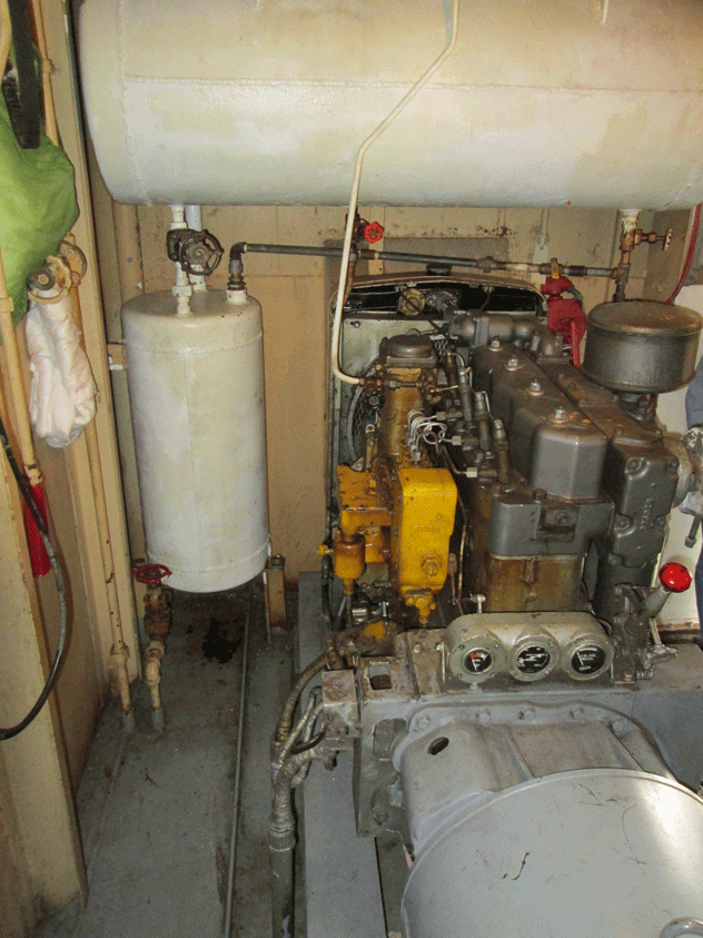 |
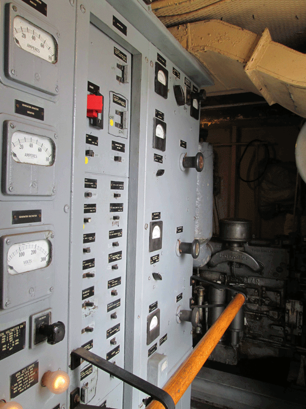
| At left the emergency power distribution board aboard SS Red Oak Victory. This was located in the same compartment as the diesel powered generator at right. |
| Below is a simplified one-line diagram of the electrical system aboard the Victory Ships as originally constructed. |
 . .
|
| Victory Ships Converted: Bowditch, Dutton and Michelson |
|
When reincarnated as survey ships the three vessels' electrical
systems were modified. While the ships' mechanical systems continued to
run on 120/240 volt DC, the two 300 kw turbo generators were replaced
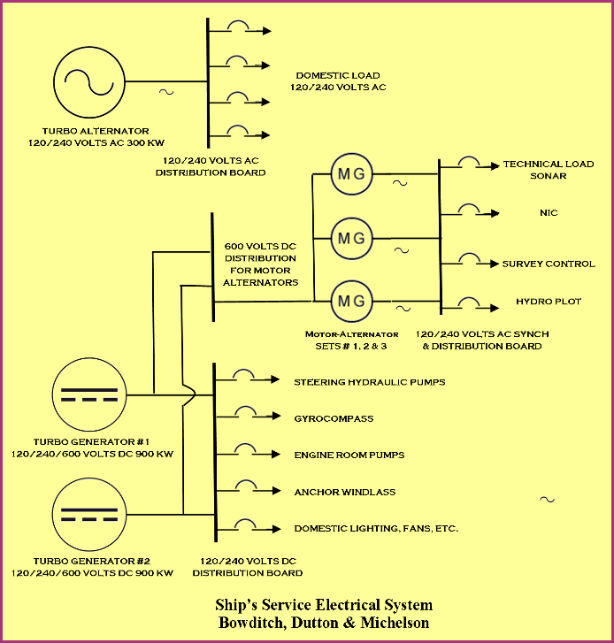
with larger units. To supply additional ship's service electricity for the larger crews and added electronics the new 900 kw steam powered generators supplied 600 volt DC as well as 120/240. An additional turbo generator, or turbo alternator, rated at 300 kw was added to the engine room to supply 120/240 volt AC (Alternating Current) for newly installed AC domestic needs. Being that the electronic gear required a stable, uninterrupted source of 120/240 volts AC, three motor-alternators and associated switch/synchroniztion board were installed. These were located in the Navy spaces on the deck below the living spaces, port side in the former number three hold. Driven by 600 volts DC, two of the three motor-alternator sets ran continuously. They were maintained by the ship's chief electrician. |
 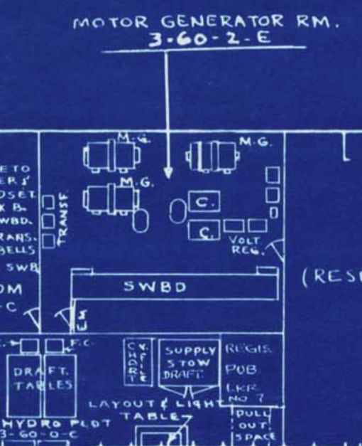 Above is an example of a motor-alternator set. The drawing at right shows the location of the three motor-alternators, powered by 600 volt DC. Also in the space were an AC distribution board and a synchroniztion panel. Alternators need to be synched in phase as they are brought up on line. On the left side of the space are a bank of three phase step up/down transformers. |
| Below is another one line diagram, this one shows the electrical power generation and distribution system aboard Bowditch, Dutton and Michelson as installed in 1958. |
 |